
And it works! It's nice when things work first time and as intended. :)
Solder a pin header to the LCD with the pins pointing out of the back.

The connections on the LCD are:
- VSS (Gnd)*
- VDD +5V*
- Contrast adjustment (VO)
- Register Select (RS). RS=0: Command, RS=1: Data*
- Read/Write (R/W). R/W=0: Write, R/W=1: Read*
- Clock (Enable). Falling edge triggered*
- Data Bit 0 (Not used in 4-bit operation)
- Data Bit 1 (Not used in 4-bit operation)
- Data Bit 2 (Not used in 4-bit operation)
- Data Bit 3 (Not used in 4-bit operation)
- Data Bit 4*
- Data Bit 5*
- Data Bit 6*
- Data Bit 7*
- Backlight Anode (+5v)
- Backlight Cathode (Gnd)
*I haven't included core colour because you may not get the same 8 core cable, just assign a colour to each asterisked connections and make pigtails to matching signals
I would normally connect a pot between VDD and VSS and feed the wiper into VO, however the display supplied with the SumPod, performs nicely if VO is connected directly to VSS (and the SumPod kit doesn't include a pot), thus I save a component and some soldering.
Using the supplied crimps and housings build the cable to connect the LCD to the RAMPS board. It should look something like this:
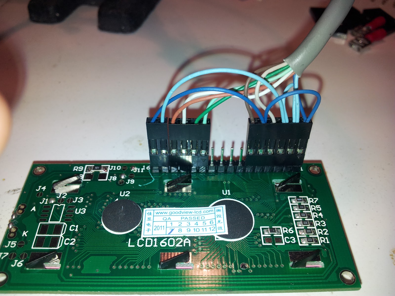
I use a small pair of ridged pliers to attach the crimps to the wires. I find it easier if the crimps are still on the strip (and less likely to drop and loose them) and when finished then remove them.

The other end of the cable will look something like the image below. I'm not sure about the distriution of crimp housing sizes, but for ease of assembly make sure you put VDD and VSS into their own two position housing.

That's all folks!
SumPod Guinea Pig zzzzz
No comments:
Post a Comment